
You are here
Building the SE.5a
“Ideally a fledgling company’s first project choice should be a small, simple, easy-to-research and easy-to-build design, not the SE.5a!”
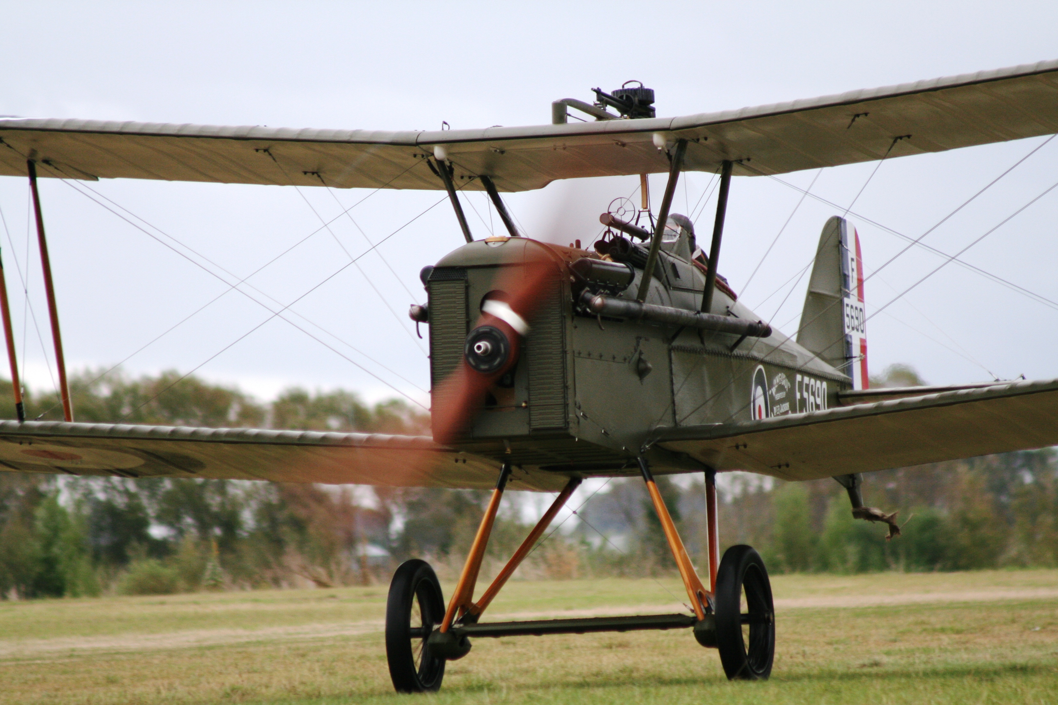
The Royal Aircraft Factory SE.5a was one of the best allied fighters of the war - but a complex and difficult aircraft to build. The problems presented ranged from an extremely complicated trim mechanism, numerous variations of built-up wing ribs, an exposed main fuel tank, and even an emergency water/fuel tank that forms the leading edge of the center section. Many small parts and assemblies, such as the Foster mount for the Lewis gun, a shock absorbing tailskid assembly and various metal fairings with compound curves also needed to be built from scratch.
An Abundance of information
We decided to build three airworthy SE.5a's, and a fourth static example to appear in a display planned for Omaka's Aviation Heritage Centre. Once the numbers were decided, the task of research began. Searching for drawings, photos and information is always easier with popular designs and there was no shortage of information on this type.
A very helpful resource was the Replicraft drawings produced by Jim Kiger, these 9 large sheets gave us an outline of the entire project and we could then research each individual part using original RAF drawings. We have discovered a great deal of information on the SE.5a that was previously unknown to many of us; triple vertical stabilizers, flaps, different wings all sorts of engine installations and many other unique prototype and experimental designs. We worked backwards a bit and started with the engines we planned on installing, the Hispano Suiza direct drive engine and then separated drawings that showed this engine installation. By the process of elimination we started to pare down the huge number of original drawings to a workable set that we believed would produce the familiar RAF SE.5a. As part of our manufacturing process and CAA requirements we also end up producing an aircraft specification, a drawing list, a drawing cross reference and of course a flight manual! Paperwork is a necessary burden at our workshop, maintaining compliance with CAA part 148 regulations. Keeping track of all the materials and manufacturing processes keeps us very busy.
 Todays’ aircraft manufacturers can purchase an engine, wheels, brakes, instruments and hardware directly from existing manufacturers. However, we built nearly every individual SE.5 part, using the same materials and processes that were utilized in the original design, e.g. Irish Linen, Ash and Spruce timbers, hand-spliced cables and original AGS hardware. Many metals are substituted for currently available aircraft quality approved equivalents.
Our skilled craftsmen have learned to combine the trades of a bygone era with modern technology. In order to stay on top of things we rely on modern technology to lend a hand, and 3D CAD design software, CAM programs and other specialized software through to CNC lathes, milling machines and routers proved invaluble in this project.
Three original Hispano Engines
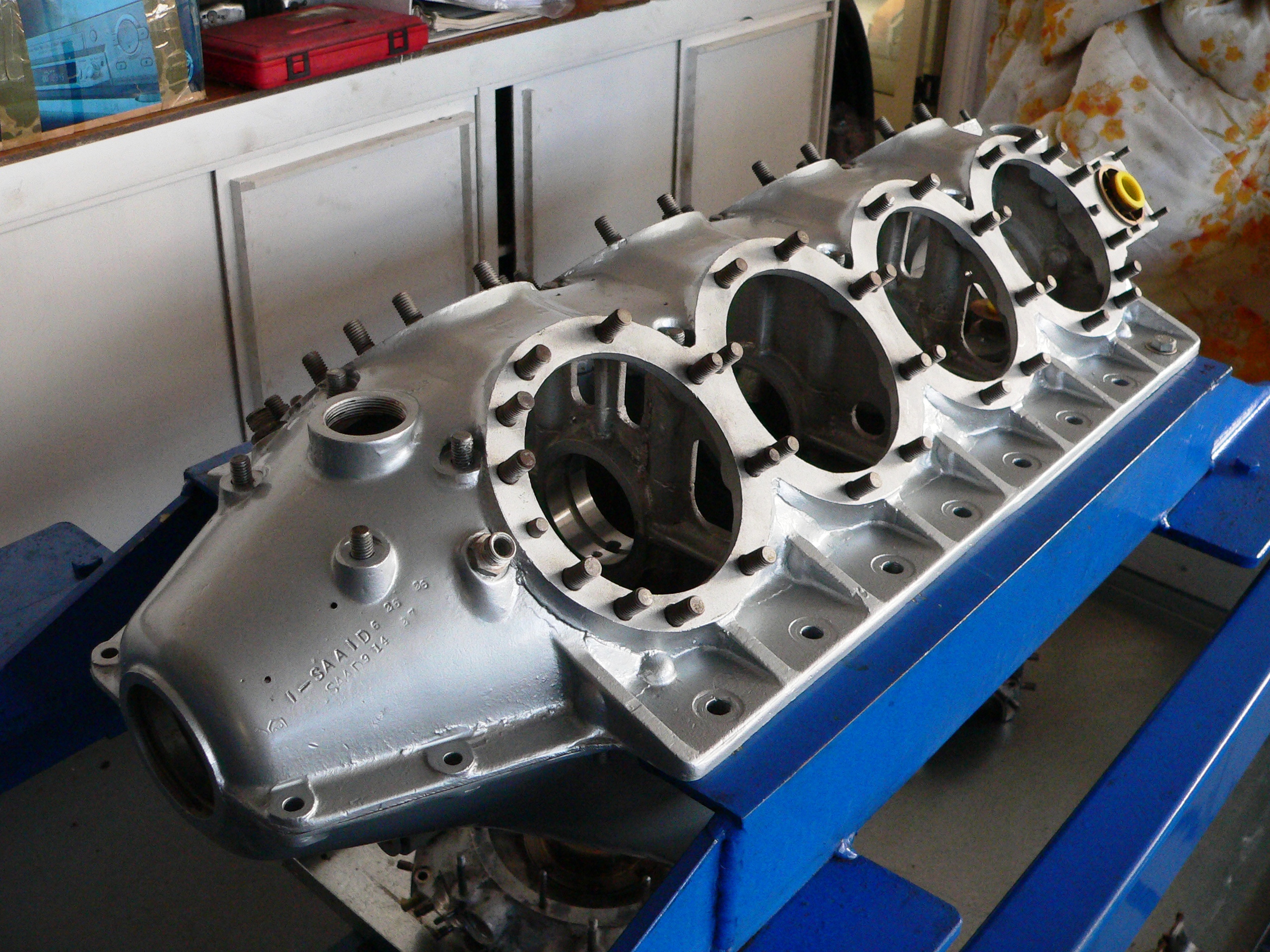
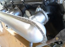
Our three airworthy SE.5a's are powered by original Hispano-Suiza Direct drive 180 HP engines. These original engines were sourced from around the world. They were overhauled here in our workshop, and test-run prior to installation in the airframes. Special tools and replacement parts had to be made in order to facilitate the reconditioning process, and to ensure we have the ability to run and maintain these engines for years to come. The restoration process differed for each engine due to the unique condition of each ninety year old power-plant.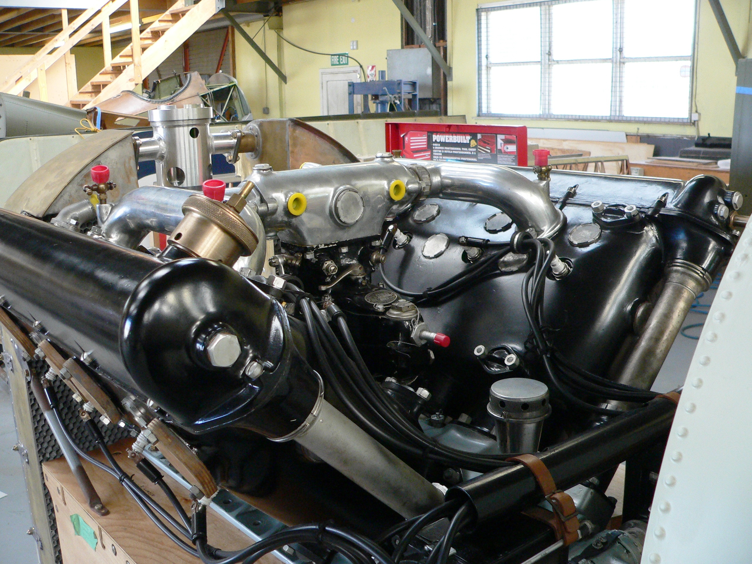
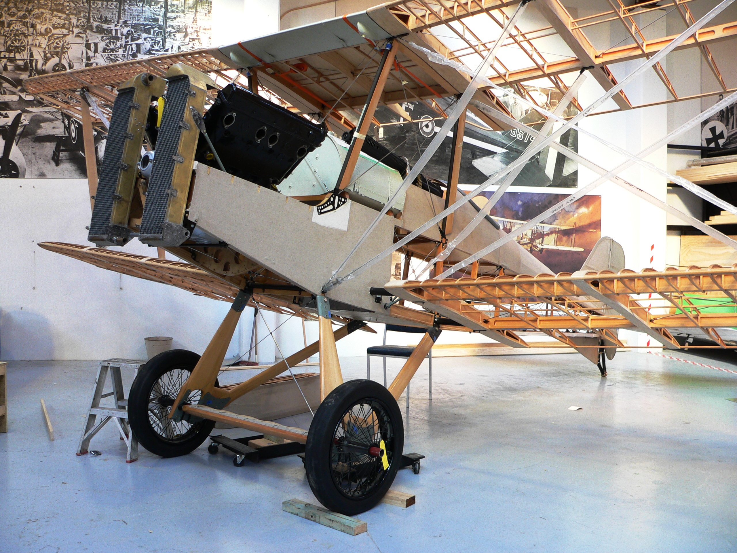
Amongst the “new” trades learned by our engineers, were hand-splicing of cable, and the use of Irish Linen for covering. The Hispano Suiza is a water cooled V-8 type engine, much different to the modern air cooled horizontally opposed aircraft engines of today. Numerous detailed aluminum fairings such as those used on the landing gear and windscreen surrounds were all required to be hand-formed, welded and made to fit. These time-consuming tasks are what makes the difference in an accurate reproduction. We like to think of them as “late model aircraft”, just rolled off the new assembly line!
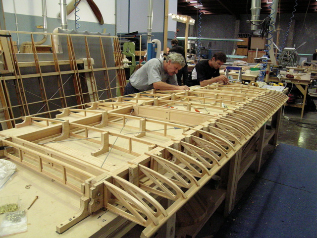
Complex Woodwork

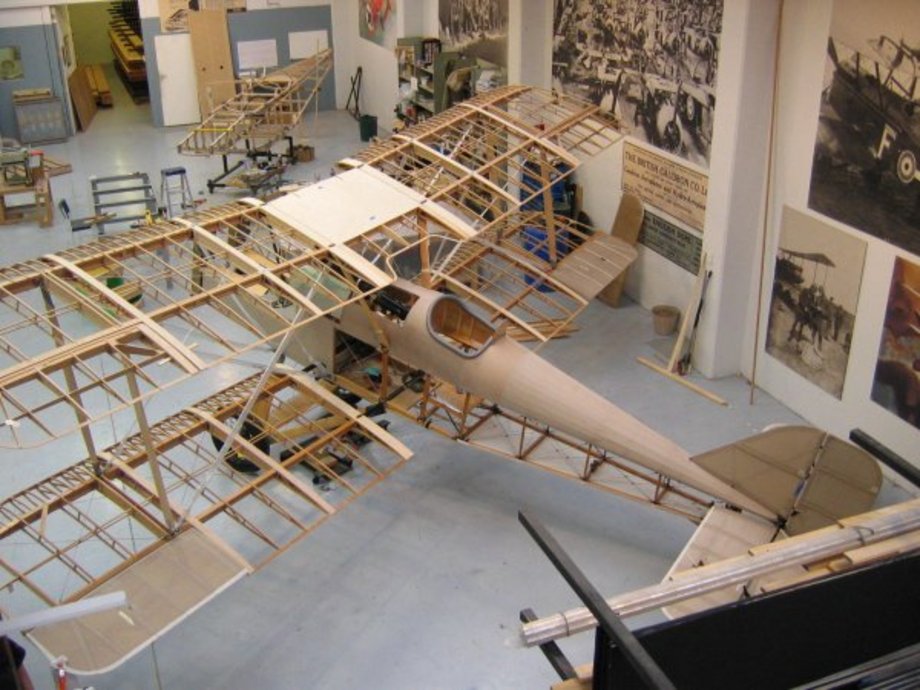
Once the woodwork was underway, the parts started to pile up rather quickly. Relatively simple components like the fuselage vertical members and individual rib parts, often require jigs to aid final assembly. This ensures the assemblies are identical to each other and able to fit more than one airframe. Because we were building several aircraft at once, it was worth spending a great deal of time building decent jigs for parts like ribs, elevators, ailerons, cockpit carlins, landing gear legs and even entire wings. Bending and laminating was also needed to form parts like wingtip bows and elevator and aileron tips.
As wooden parts were completed, we had to have associated metal bracketry on hand to test fit and finally assemble parts. We had good results laser cutting metal parts and hand forming them into finished clips, brackets and supports. It took many months to perfect the process of laser-cutting parts, but saved many years worth of labour!
 A single part often required experimentation and study before it could successfully be produced. For example, a simple wingtip, formed from laminated American white ash would be produced in a form and checked to see how much "overbending" was needed to end up with a part that matched the drawing exactly. This type of part is constructed by gluing several thin layers of hardwood together around a form and once dried, machined to shape. Many of these formed parts are then laminated to other parts such as spruce leading edges. For thicker hardwood parts steaming was required. With steaming we discovered that air dried timber versus kiln dried timber have different bending properties. Glue tests are always made and we retain samples of every batch of glue we mix and the parts that have been glued with each mix.
The wooden cabane struts and interplane struts were all handcarved on the SE.5a’s - tasks that we now have replaced with modern CNC technology. We have a large CNC router that we use for many wooden parts where repeatability and precision are required. The router can “rough” parts in a fraction of the time it would take to hand-form them, and then we simply hand-finish the machined parts. Murray Hunter writes about working with hand tools to shape the SE.5a struts: "Working with hand tools is a pleasure in itself, utilizing skills that are largely gone in this day and age. First I made the profile shapes of the streamlined aerofoil struts at various points along the length of the strut, then marked the points on the bare timber, then I planed the shape with a hand plane and finished each one with a compass plane and a spokeshave and finally with sandpaper. I must say that it is a pleasure to be working on these aircraft.”
Accessories

 One aspect of aircraft construction that is often overlooked are all of the “accessories” and minor details that make these aircraft so special. In the case of the SE.5a we rebuilt a starting magneto that protrudes through the side of the cockpit for an engineer to operate and assist in starting the original Hispano engines. We also built our own water temperature gauges, and almost every other cockpit instrument. Starting with our own aluminum bezels and laser cut pointers we fitted many modern reliable instruments and made them appear identical to the originals. We also fabricate hand air pumps to pressurize the fuel tank and made our own Aldis sights. The cockpit is also adorned with several spare Lewis magazines and accurate replica radiator shutter bowden controls and a proper Sutton harness.
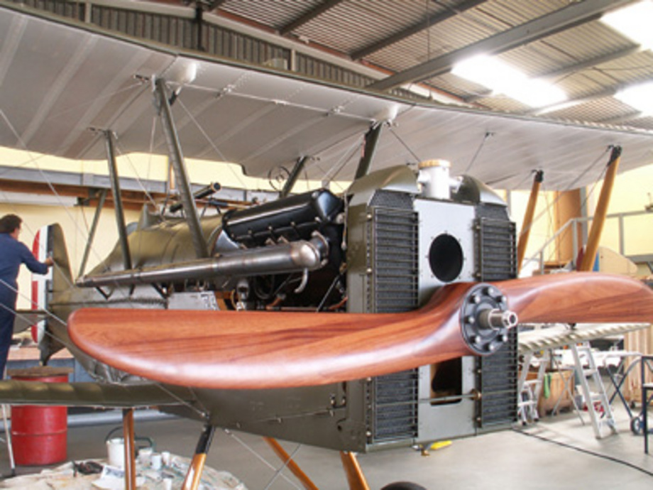 We are lucky to have access to an original SE.5 propeller, which we scanned into a computer and machined exact copies from laminated mahogany for each aircraft. The wire spoke wheels, the Palmer wheel covers, the windscreen and even clear inspection windows in the fabric surfaces, all had to be made. The SE.5a is a fighter and as such, it could be said the guns are the heart of the airplane. The Lewis gun and the Foster mount are highly visible above the center section. Foster gun mounts are impossible to find, and real Lewis Guns create legal problems - so we decided to manufacture our own. We made operating Foster mounts from original drawings and retained the option of fitting a real blank-firing gun for airshows. However, we also worked out an effective technique for replicating aircraft guns, and these reproduction Lewis and Vickers machine guns decorate our SE.5a's.
“If I had any doubts about the reliability of the Hispano Suiza engine, I would not have flown the SE.5a across the Cook Strait to attend the Classic Fighters Airshow”
The experience of making these SE.5's led to us devising techniques to mimic what was done in the past. We hope this has opened the door to recreating many other aircraft from this period. Our four SE.5a's are nearly all completed. The static aircraft is on display in “The Aviation Heritage Centre”, Blenheim New Zealand, depicting a scene in which "Grid" Caldwell suffered a mid air collision and was forced to bail out from his aircraft over the trenches. The first airworthy example made its maiden flight on March 26, 2007. Vintage Aviator test pilot, carried out the test flying. “It is the finest example of a WW1 fighter I have ever flown! It is comfortable, maneuverable yet stable, fast and easy to fly. The cockpit is warm, not too windy and the visibility is very good even for a biplane. Best of all, the engine inspires confidence, it develops a tremendous amount of power, responds well and is extremely smooth and so far, very reliable. If I had any doubts about the reliability of the Hispano Suiza engine, I would not have flown the SE.5a across the Cook Strait to attend the Classic Fighters Airshow”. The second aircraft is currently undergoing its CAA flight test program. The third flying example is due to be finished very soon.

