You are here
Bentley 230hp BR2 Engine Build
"Because of its physical size and the fact that this was the last Rotary to be used by the RAF, the TVAL team were quite excited about this project."

The BR2 was the most powerful rotary to see service and produced 230HP @1300RPM.
It has a bore size of 140mm and stroke of 180mm giving a total volume of 25 litres (1500 cu.in) and weighs in at only 220kg.
Because of its physical size and the fact that this was the last Rotary to be used by the RAF, the TVAL team were quite excited about this project. While a number of people have successfully made ¼ scale versions of this engine, quite a few design changes were made with the drawings to be able to achieve this, so when compared to original parts a number of items are quite different. For this reason the use of these ¼ scale drawings to build a full size engine was definitely not an option, as the completed engine would not at all be accurate, and would likely weigh more than an original.
For TVAL the first problem was to locate an original engine to copy. This was not easy, however one was eventually located and its owner generously agreed to lend it to us. Once the engine arrived it was carefully dismantled, cleaned, each part photographed, and drawings made.
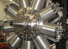
One of the things Bentley had wanted to try while working for Gwynne’s was the use of aluminium cylinders; he first tried this on the BR1 and as it was successful incorporated this feature into the BR2. These had thin cast iron sleeves pressed into them. This use of aluminium significantly reduced the rotating mass when compared to the alternative of steel as used on other smaller rotaries. Because of the number of engines being produced during the war, items such as the crankcase would have been machined from a forging. Because of the smaller number of engines being produced by TVAL we chose to machine these from billet steel.
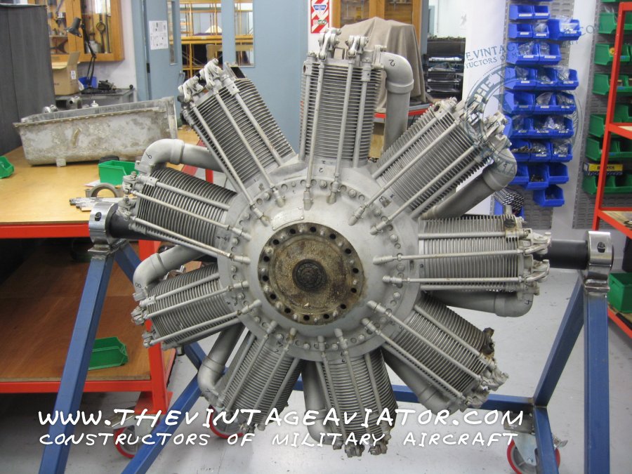
One of the difficulties with machining from a billet is dealing with the enormous weight of the pre-machined part; the finished item probably weighs less than 10 % of this original piece! The cylinders on the Bentley are spigoted into holes in the crankcase which are spaced 40 degrees apart and held in position by long bolts that extend all the way through to the cylinder heads.
The cylinder heads were also machined from a billet; each one having five cooling fins machined around its circumference and as per the original the valve seats machined directly into the head. As the BR2 runs twin magnetos, two spark plug bosses were incorporated into the leading side of the heads. As the original pistons were made from cast aluminium, it was decided to manufacture the new pistons in the same manner. Our engineers set about manufacturing dies to achieve this. The castings were then CNC machined and batched into groups of the same weight. The pistons are quite interesting in that they each have a large cutaway on one side so that they will clear the neighbouring pistons when at bottom dead centre, these areas of the skirt get as close as 1mm from each other.
An excellent design feature of the Bentley is the cam gearbox assembly. This was designed to be easily removed from the engine as a unit, which makes it effortless to service - especially when compared to some of the other rotary engine designs.
The valves are opened using a very clever system inside the cam gearbox, the internals look much like a rotor type oil pump. This arrangement turns with the engine albeit at a different speed, and as it rotates it lifts the pushrods to open the valves.

The master rod was a difficult part to machine and required both turning and milling. It has 8 holes, 40 degrees apart that connect the slave rods to the master via a hardened wrist pin. It also has a number of holes strategically placed to direct oil to the wrist and gudgeon pins. If you’re a machinist you will understand that machining parts like this is a nerve-racking job and a wrong cut at any point can render the item useless. All nine rods are of tubular section steel and with the exception of the master rod are bushed at both ends. The master rod itself revolves around the crankpin on two large bearings.
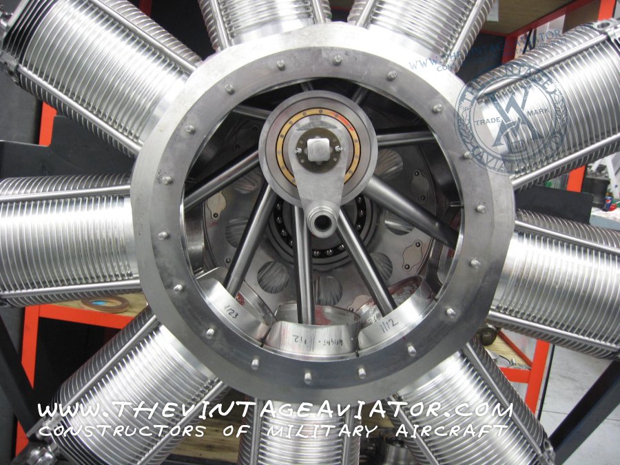
The Crankshaft is built up of two pieces - the main crank and the Maneton or short end. This again was a difficult and time consuming part to manufacture and required a lot of care and accuracy in doing so. Because of its function in a Rotary engine the crankshaft must be of the highest quality. As is normal in Rotary engines it forms a means of attaching the engine to the airframe, it forms the spindle that all of the rotating parts revolve, and provides a fixed
point (the Maneton) through which the combustion force acts.
The earlier BR2 engines were fitted with Clerget type oil pumps while later engines used the Le Rhone type. TVAL used a Le Rhone type oil pump on their engine; this also having been manufactured from an original unit. Although these “bolt” on items are smaller they still require a large amount of time and effort to build and have quite a number of parts that require manufacture. After completion of these pumps they were test run for a number of hours and the oil flow checked to ensure the correct amount was being supplied.
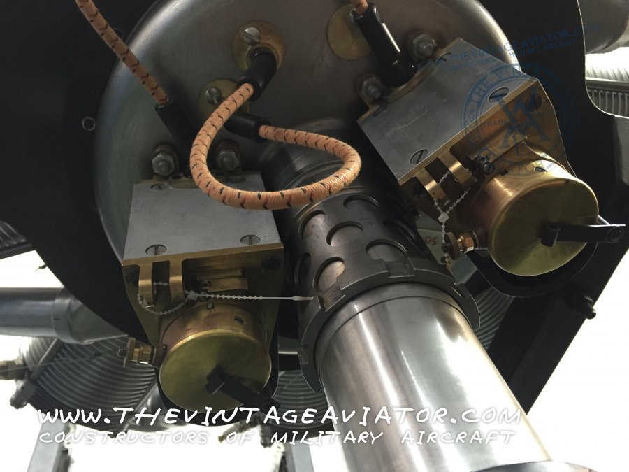
Magnetos for Rotary engines are extremely difficult to find and after some deliberation it was decided to manufacture our own. This proved to be a huge undertaking as it required not only the manufacture of various metal parts etc, but also items such as slip rings, condensers, carbon pickups, point’s assemblies, magnets and bearings. On top of this we also had to build and successfully wind armatures. A considerable amount of time was spent in research to find the correct materials, this was very important particularly when it came to manufacture of the armature core.
For the actual winding of the armature the services of an electrical engineer were employed and after a number of test windings of various turns and wire size, a full test of a completed magneto was undertaken with excellent results. This first unit was test run for 100 hours during which time it was exposed to temperatures from 0⁰ to 100⁰ Celsius to ensure there was no electrical breakdown.

Fuel control on the BR2 is via a block tube carburettor and is used in conjunction with a Tampier valve. The throttle is a brass slide that increases or decreases airflow through the crankshaft, as the throttle is opened and air flow increased the tampier must also be opened to allow more fuel to enter through the hollow crankshaft. This creates a rich mixture in the crankcase which is transferred to the cylinders via intake pipes as the intake valve opens.
TVAL spent a considerable amount of time and effort to ensure that the correct materials were used on this engine build and used non destructive metallurgy on a number of items to confirm the original. Although very expensive this proved to be invaluable and confirmed its worth in the final result.

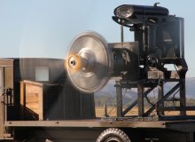
Once the new engine was completely assembled it was mounted on a test bed and with much anticipation and excitement the propeller thrown for the first time. The engine burst into life much to the pleasure of those watching; it is quite something to see such a large Rotary spinning at 1300 rpm, and the sound is incredible!
After this initial start the engine was run for 20 hours to fully test all of the internals, at which time it was stripped and closely examined for any premature wear. The final result was a 100% accurate, reliable, recreation of an engine that some say was the peak of Rotary engine development.