You are here
Oberursel 110hp UR.II Engine Build
Locating plans or enough reference to build decent copies of WW1 aircraft is hard enough, but it's even more frustrating if the information exists but the correct engine doesn't. Sometimes it means that a more recent engine is substituted. This can be a good solution if you want to end up with an aircraft that is reliable and can be maintained without too much trouble.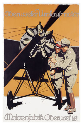
However, it's only when an aircraft is flying with an engine from 1914-18, that you can really see and hear history coming to life. This attention to history is becoming more important for a growing group of aircraft builders, and it's providing a lot of satisfaction to airshow visitors.
The Vintage Aviator is able to build engines under it's NZ CAA certification, as well as aircraft, and we decided to test the realities of building a complete reproduction engine. We have actually started work on several engines, based on the schedule of aircraft we're working on. The first of these to be completed was the RAF 1a, which is needed for our BE.2f restoration. However, when it was decided to build several more BE.2 variants, we re-visited several aspects of the way that engine was made and a more authentic example will be completed soon.
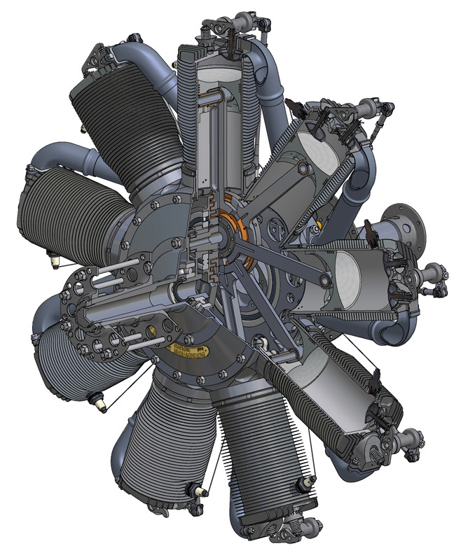
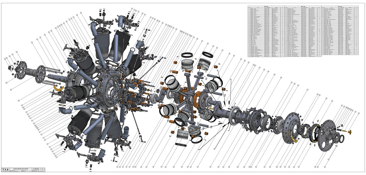
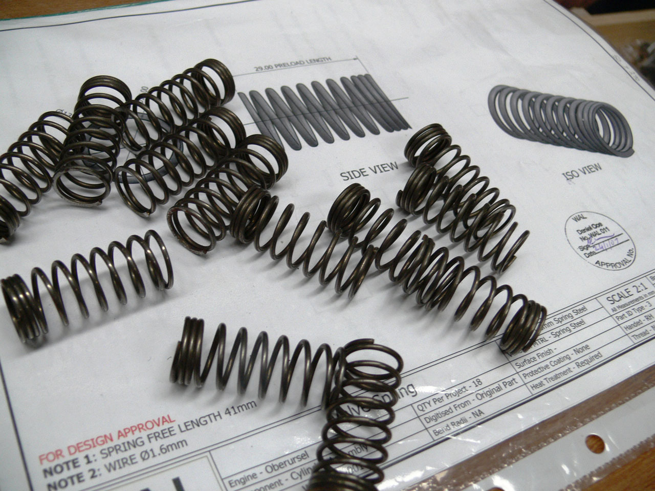
Our second engine to run successfully is the German Oberursel UR.2 rotary engine. The original is very rare, and yet it powered the Fokker Triplane - surely the most popular WW1 aircraft in the vintage aircraft building community. We were lucky to have access to an original engine, to examine and reproduce. Using this engine, we produced an entire set of construction drawings, modelling every part in CAD. We used this information to produce a wonderful exploded-view wall poster - and thought briefly about giving up at that point. It's a lot of parts! What kept us going was the fact that WW1 era engines are getting so rare and that at some point there has to be the possibility of introducing newly manufactured examples into our tiny hobby. The opportunity to see an exciting, previously extinct aircraft, take to the skies again with a rare aero engine became the ultimate motivation.
The Engine Build
The engine we borrowed arrived in a box, several boxes in fact! The engine we were to reverse engineer had already been taken to bits, we had no idea if all the parts were there or if they would even fit together. The Initial challenge was figuring out the principles of rotary engines whereby the complete engine rotates around the crankshaft, so assembling this example we had to make sure we had all the components of a working engine.
Without an “owners” manual or even a parts manual we began to research the history and manufacturing of the Oberursel engine. Very early on it became apparent that it was based on the LeRhone 110 engine for which we had a set of partial plans and hence were able to lay out peculiar looking parts in a rough reference of the assembled engine. This provided us with important information such as; complexity of parts, suitable material strengths and tolerance. We laid out a project plan based on complexity of parts and assembly sequences.
The German tolerances and machining processes for the era were admirable as we learnt while measuring and modeling the parts to CAD. Despite preconceptions held, the advances in technology over the last century were more of a hindrance than help during manufacturing. Engineering workshops operating in today’s era that produce complex parts in low numbers are rare indeed. To replicate most parts we were required to follow the original manufacturing processes which added countless hours and complexity to what appeared on initial inspection to be simple parts.
This was the first of our engine projects to be fully modeled in the computer. We were able to assemble, check fits and even rotate the engine to check for interference before all of the parts were even finished. By manufacturing groups of parts or sub-assemblies we could reduce the number of reworked or incorrect parts and get a better understanding of how each component works relative to other parts in the engine. The LeRhone drawings were also invaluable during the construction, many of the Oberursel parts are interchangeable with LeRhone parts and some just require additional machining or lightening.
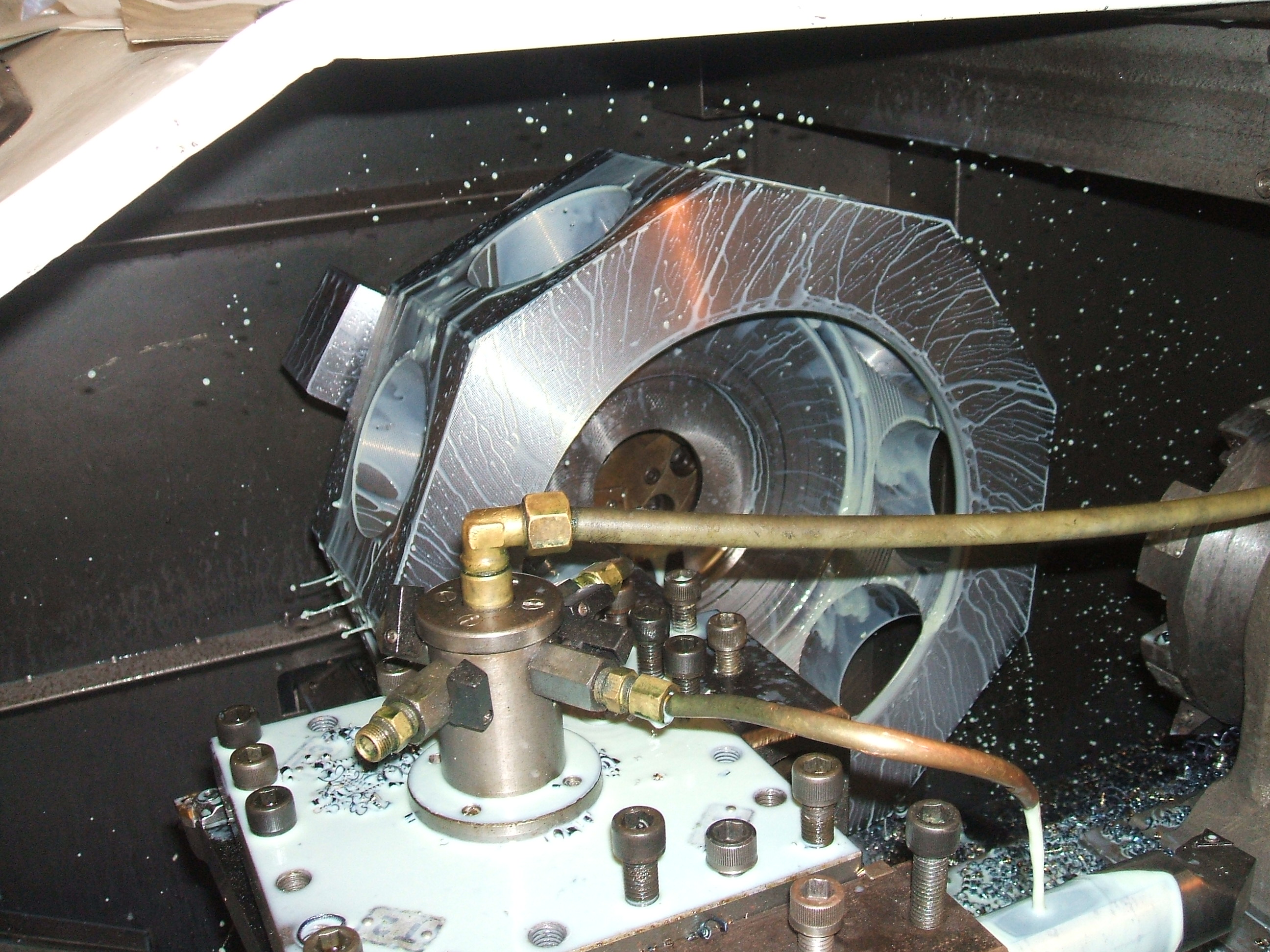 The starting point for us were the biggest and most complex parts such as the crankcase, cylinders and crankshaft. If we couldn’t reproduce these parts there would be no point in continuing. We began measuring and drawing the crankcase and enlisted the help of another company that has a Coordinate Measuring Machine large enough to check our measurements and confirm all critical points were located correctly on our model. It took over 100 hours of measuring to draw this one part of the puzzle. Next we discovered features of the cylinders that were going to be manufacturing nightmares, a convex combustion chamber and tapered cooling fins and a very thin wall thickness when finished. Nevertheless after metalurgical analysis of the original material we ordered steel to begin making these parts.
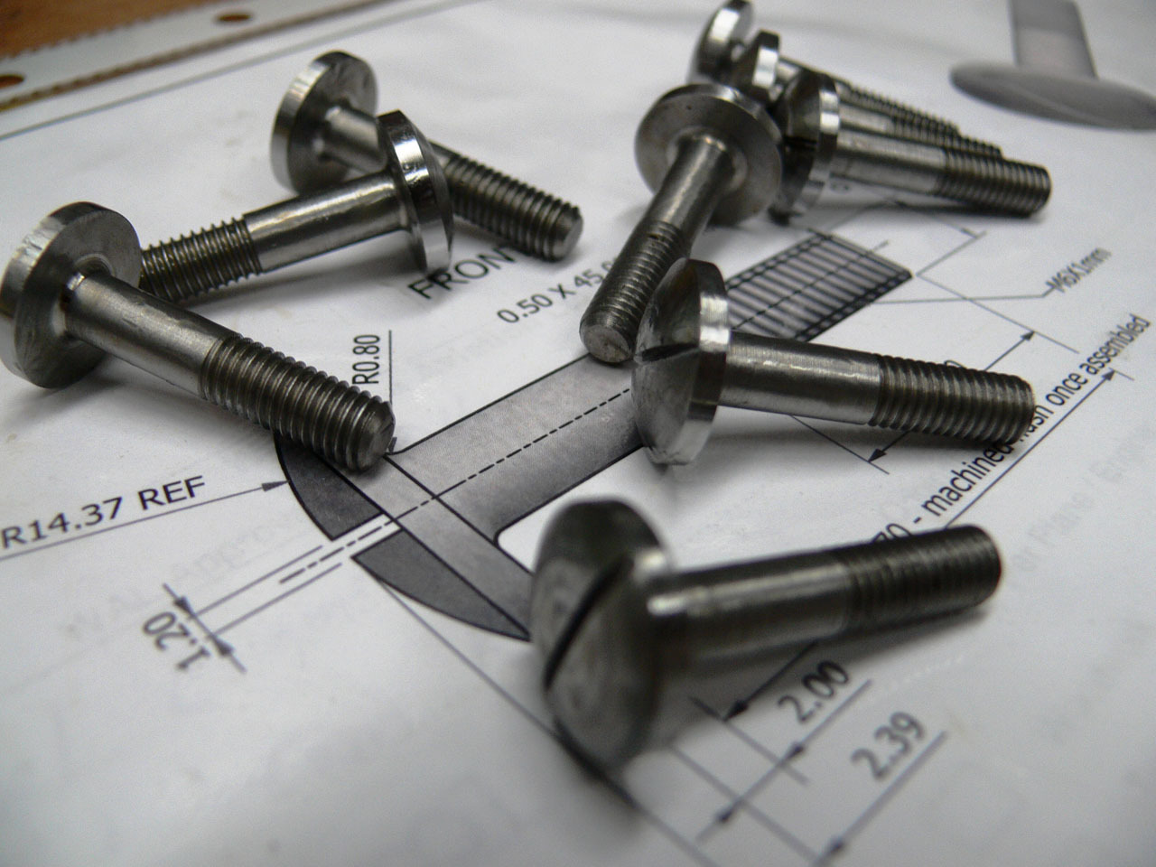
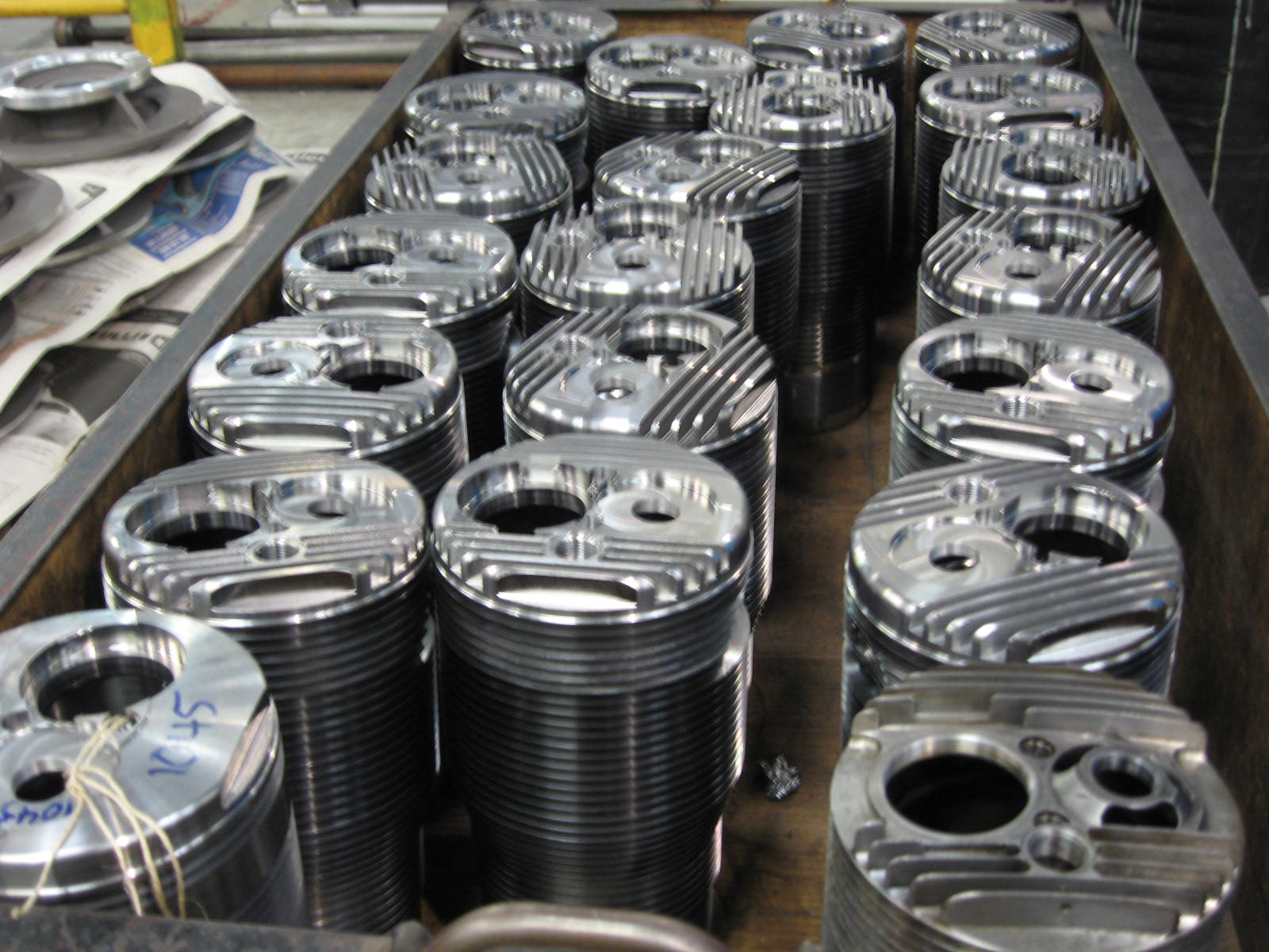 Three months later we had our first two crankcases, two crankshafts and two sets of cylinders ready for inspection! While these parts were being made our designers were busy drawing the smaller parts and our machine shop was making everything from nuts, bolts, studs, to valves, intake housings and cylinder lock-rings. We soon discovered that there are 185 unique parts in one engine and each engine requires a total of 1209 parts ....and this does not include the accessories (oil pump, carburetor, magneto) Once the “bare” cylinders passed inspection and dimensional checks, additional parts such as the exhaust valve guide, valve rocker pedestal and intake housing could be fitted to complete the cylinder assembly. The exhaust valve guides were manufactured on a CNC mill-turn and the intake housings and rocker pedestals were made in our Haas five axis machining centre.
{gallery_attach:123:flowview}
When it came to sourcing ball bearings that were available nearly one hundred years ago we were not surprised when we could only procure about half of the size and type bearings we would require. After an exhaustive search we decided to have several custom bearings made just for this project, in some cases we had to order minimum quantities that far exceed our requirements. This further adds to our company capability, we can now provide spare parts and overhaul these engines with the parts we have made and the tooling we have fabricated.
Fortunately we have just purchased a rapid prototype machine that allows us to “print” sand casting patterns for non ferrous materials, with this machine we were able to go directly from CAD model to casting pattern! 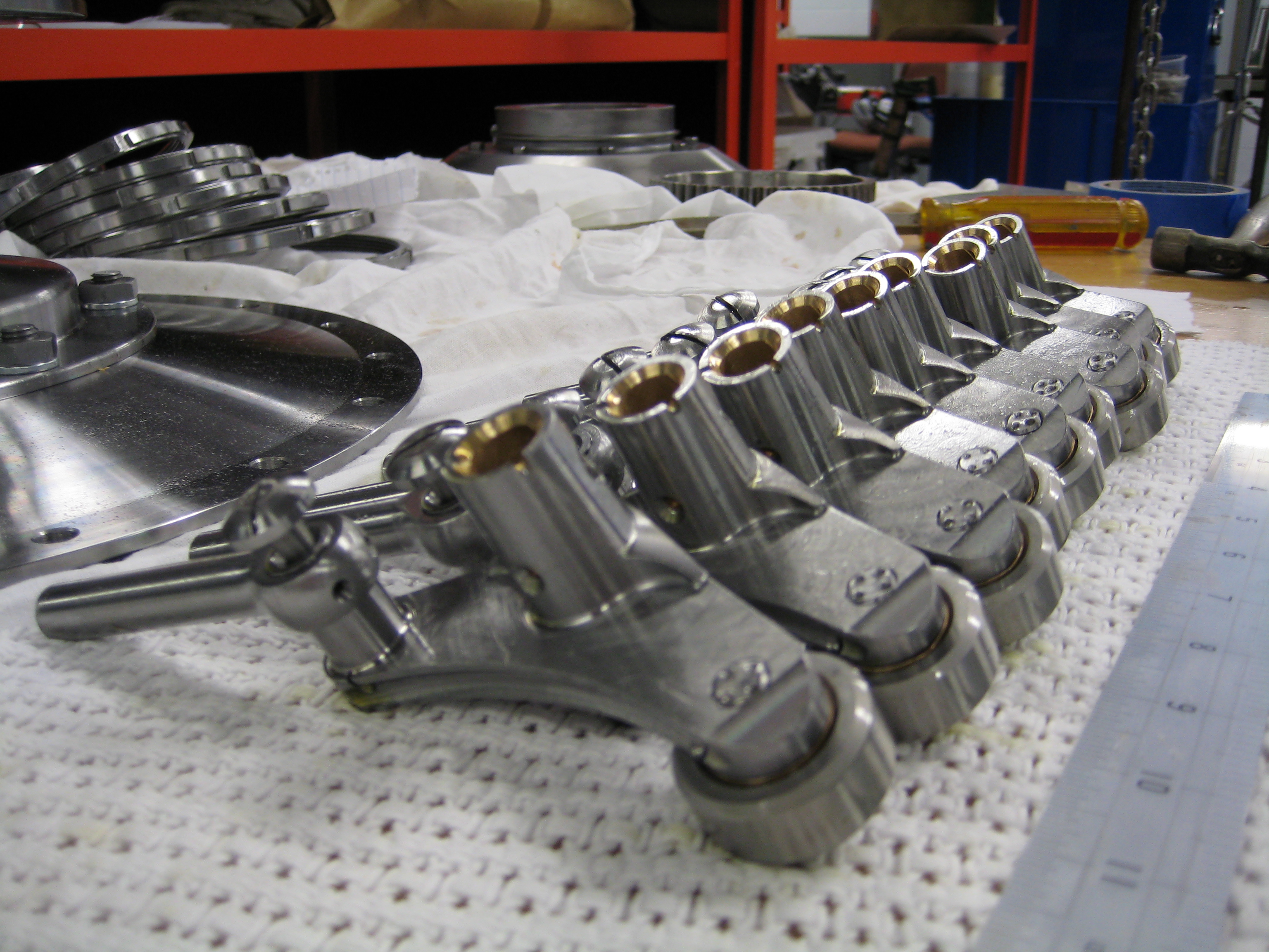 This is relatively new technology that allows 3 dimensional printing of parts. This made making the aluminum pistons, oil pump bodies and tampier housings very easy and cost effective. Fortunately we had some original accessories to run our two engines with, and we could take our time to produce new reproduction Block-tube carburetors, oil pumps and magnetos, which are all underway at this time.
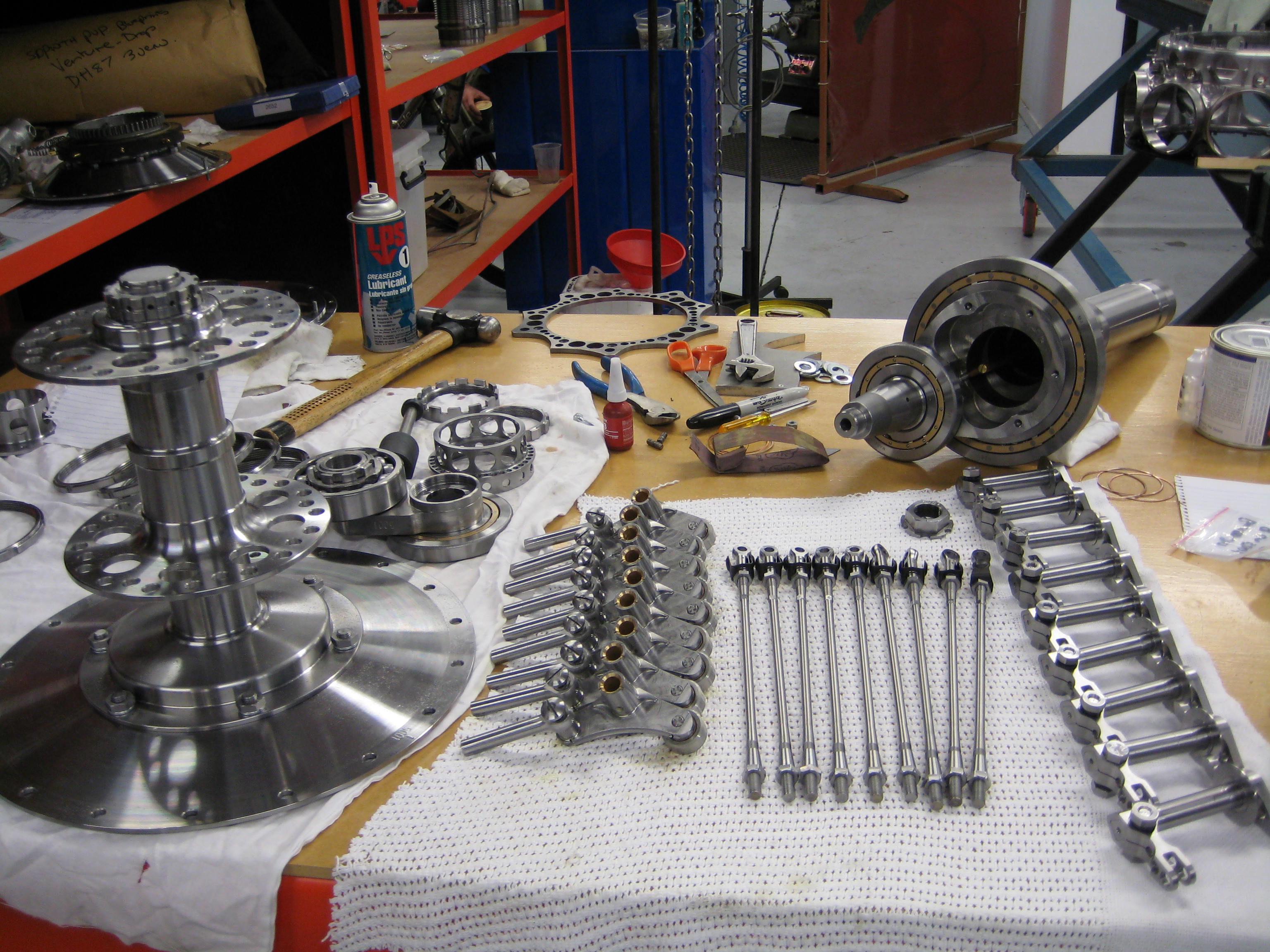
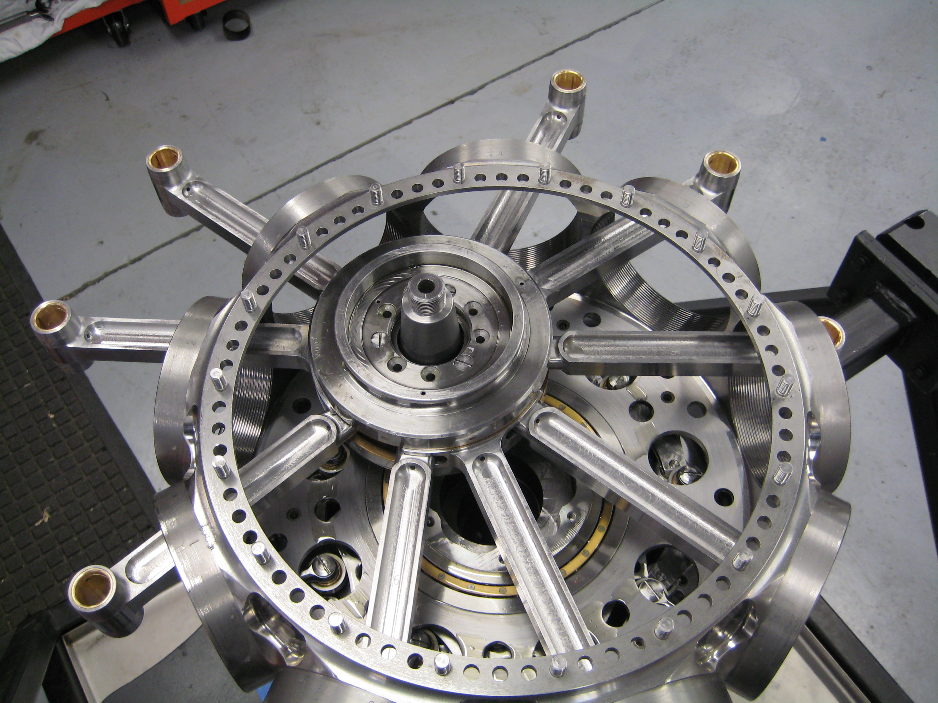
As individual parts were completed, assemblies were started which required hand fitting and further fabrication such as; grinding, honing, linishing and peening. Most assemblies could only be completed once assembled and machined to the correct size. Some of these assemblies were very simple like the pushrods, other assemblies were quite complex like the cam rockers. The cam rockers consist of some twelve precision fit individual parts, a few of which needed to be ground to size and carefully fit during assembly. We then test fit the large main bearing that supports the crankshaft in the crankcase and began to fit the cam rings and gears along with the front and rear covers, very quickly it began to look like an engine!
During the entire process we followed our company protocol which makes certain we document all drawing changes and revisions, this enables the CAD draftsperson to incorporate both manufacturing and assembly revisions in our drawings. We now have a complete set of drawings for the Oberursel UR.2, something that may have been lost up until now.
A few parts caused us concern since we had no concrete evidence of how they were constructed and we couldn’t risk destroying an original part to determine how it was made. We turned to X-ray technology to see inside of a few components. This was a big help when building the distributor rings and also the main thrust bearings. We could confirm our designs without a doubt and didn’t have to sacrifice any parts. These are among the last parts to be made and when they were finished it was time to assemble the engine with all of the components and sub-assemblies. This would only be trial fit to determine gear lash, any interference among parts, and that everything worked as it should.
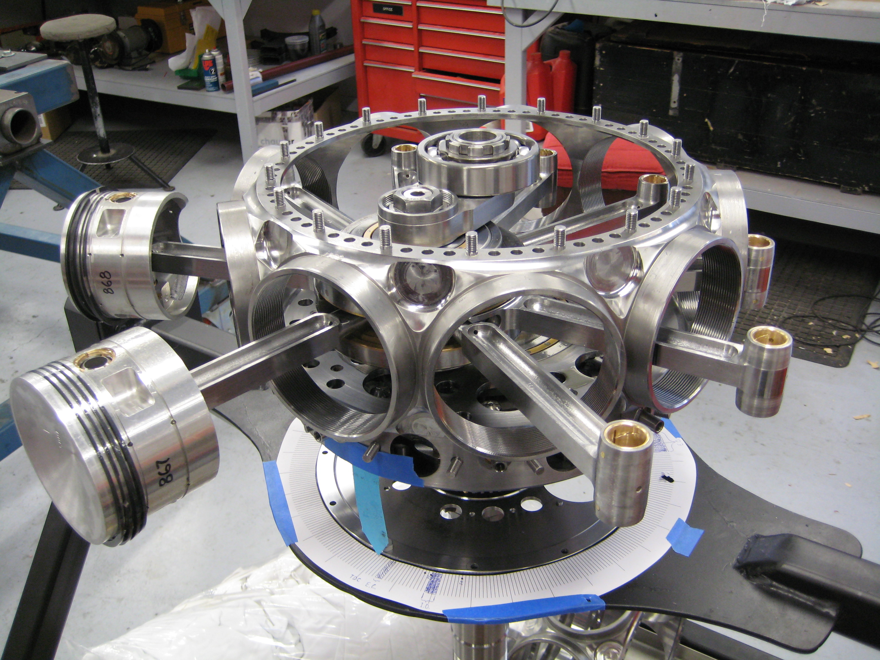
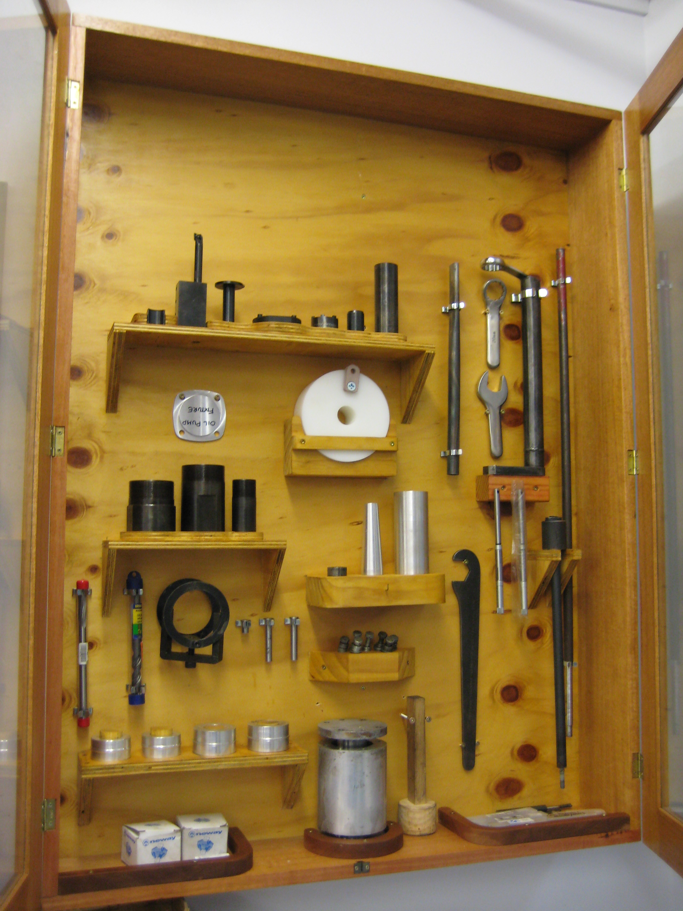
We built up the engines on purpose-built stands that allowed either end of the engine to be worked on and also allowed the entire engine to be tilted or swung upside down. A very accurate degree wheel is an integral part of the assembly stand, this allows us to check the valve timing and also make sure the cam assembly functions properly. In addition to the stands, a number of special tools were made to work on these engines. Tools and spanners to attach the short end of the crankshaft, tools to tighten the intake housings and exhaust valve guides and many more. We made a complete cabinet full of special tools. 10 months from the start of the project to our first engine was ready to run!
Testing
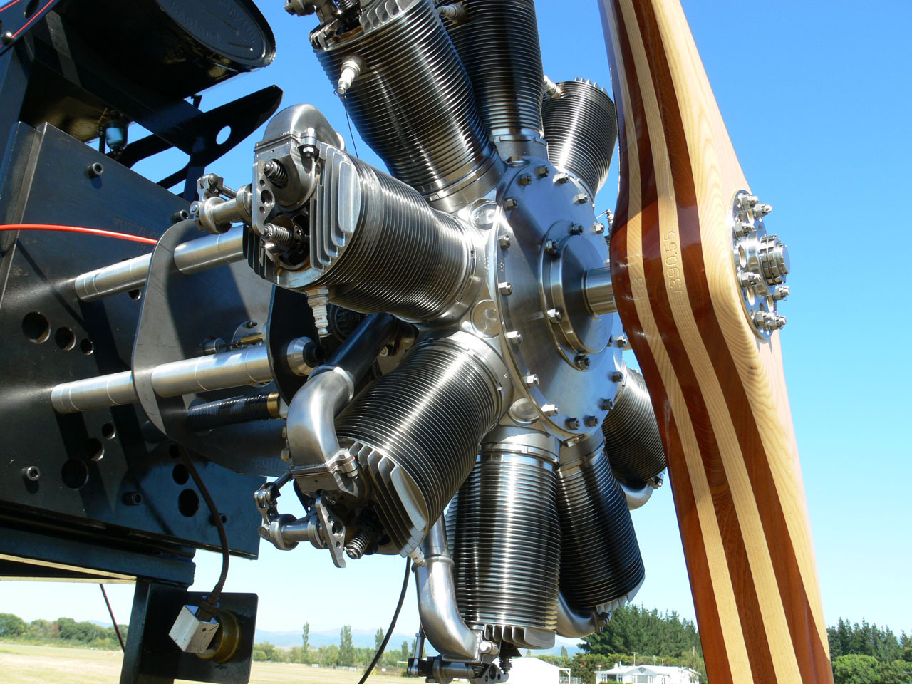
We then mounted each engine on a test bed that could measure the torque output and proceeded to run-in the new Oberursels and test run the freshly overhauled engine that was loaned to us. Fred Murrin supervised the test run program. The first engine has already run eight and half hours without any problems, and has been torn down for inspection and reassembled without any discrepancies noted.
It won't be long before these two engines are installed in flying aircraft and the second phase of the test program will begin.
